Membrane Keypads Custom Design & Manufacturing
In a world where technology and innovation has become a necessity, the membrane switch has developed into an efficient solution to facilitate a low voltage, low current and momentary electrical contact that transmits a command from a user to any device. Compared to the most common switches we see at home — the light switch, membrane switches are operated by generating a finger tip force in the keys within its panel. Often used with microprocessor based control systems, membrane switches have become an essential part of modern instrument, machine and appliance panels that have specialized functions in our daily lives.
Origins of the Switch
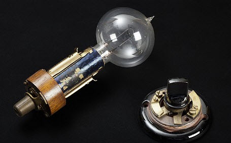
The history of the switch goes hand-in-hand with the invention of the electrical circuit. Alessandro Volta, who was the inventor of the battery, was unclear if he used a switch when he managed to generate a consistent flow of current from his voltaic pile in 1800. However, it was during the time when the electrical light was invented, when electrical circuits took the center stage. When Thomas Alva Edison invented the first commercially practical incandescent light bulb in 1879, he eventually pioneered in building the first commercial electric utility turning the switch on in 1882 to open America’s first power plant lighting up 59 households in lower Manhattan.
However, the invention of the first light switch is credited to John Henry Holmes in 1882. This initial light switch embraced the “quick break technology” that solved the problem of electrical arcing each time the switch is turned on or off. This arcing caused a friction between the switches’ contacts that results into residue build up diminishing the functional life of the switch. With this new method he called “quick-break”, he made sure the contacts hold together quickly and without enough pressure so that the switch actuator would not break easily. This is the same concept that modern day electrical switches are maintaining today to power up billions of homes around the world.
Making Way for Membrane Keypads
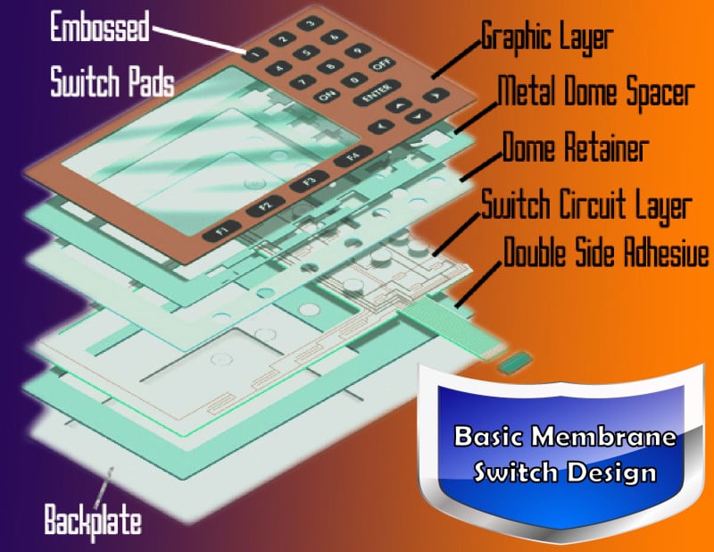
When different electronic products came into existence more than 30 years ago, the membrane keypads were used as the operating panels. These push button keypads had problems because of undesirable tactile response. As technology developed through the years, the modern membrane switch have evolved to avoid these problems by customizing how these switches are built to fit the product and how it is used. Most often, they are now composed of 4 or more layers of substrate joined together like a “sandwich” and attached by a pressure-sensitive adhesive so that all you see outside is the graphic interface.
Contact Bounce | 5 – 30 mSec |
Contact Resistance | 10 – 500 Ohms |
Life Expectancy | 5 x 10⁵ – 10 x 105 cycles |
Open Circuit Resistance | >10 Meg Ohms |
Operation Current | >100 mA |
Operation Force | 30 g – 500 g |
Operation Temperature | -20 °C – +75 °C |
Operation Voltage | <35 VDC |
Switch Stroke (travel) | 0.1 mm – 0.6 mm |
Table 1. Membrane Keypad Standard Specifications
Customized membrane switches are often built to match your device. Graphic overlays can be screen or digitally printed to match the surface of the device where it will be intentionally placed. These can have embedded LED displays and could employ tactile/nontactile feedbacks when needed. The most vital layer of the membrane switch is the printed circuit board (PCB) that can be composed of integrated circuit, which controls the electrical responses need for any device to function.
Flat Type (Non-Tactile)
|
1. Graphic Overlay 2. Upper Spacer with Adhesive 3. Printed Circuit 4. Back Adhesive | Dome Type (Tactile) |
1. Embossed Graphic Overlay with Circuit 2. Spacer with Adhesive 3. Lower Circuit 4. Back Adhesive |
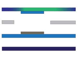
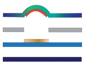
Table 2. Tactile vs. Non-Tactile Membrane Keypad.
Most modern circuits inside a membrane switch are manufactured using computer-aided design (CAD) programs. The majority of the circuits implemented in digital computers are particularly sophisticated that they employ millions of transistors, so using CAD would be the only simplest way to layout the complicated functions they are supposed to make. The circuit designer starts off with a standard specification of a circuit should perform and the CAD program sets out the intricate pattern of interconnections to produce an intended command from a user to the device.
Benefits of Membrane Switches
Since membrane switches are more lightweight and low profile compared to common light switches, these can be embedded to virtually any device that needs various control features. For example, the microwave oven needs different amounts of heat with different time considerations in order to heat food so these membrane switches can control all these functions without difficulty. These switches are resistant to shocks and vibrations so any moving device can perform normally without breaking the facility of the switch. The designs now also allows the addition of electronic components into the flexible switch substrate so it can adapt to some special attributes needed for a specific control panel system.
The electrical performance of these switches can also be varied depending on the specifications set for a particular device. The most common are that the loop resistance should be be less than 100 Ohms, while the open circuit resistance should be set at the minimum of 50 mega Ohms. The membrane switch should be able to function within the standards -20 °C to +75 °C as its operating temperature. The contact rating should stay within 100 Milli-amps at 28 VDC Maximum, while the contact bounce should be 5 milliseconds nominal. Modern membrane switches have also adapted to become water/moisture proof, heat/cold resistant and the front panels are designed so that they are easier to clean.
The American Society for Testing and Materials (ASTM) has developed international standards for membrane switches. For example, they have developed methods in determining the tactile ratio, contact closure rating and the standards for the effective visual inspection of membrane switches.
Applications
There are several industries that employ membrane switches in their devices. On common household appliances, the membrane switch can be found on washing machines and microwave ovens. More common on digital versions of these appliances, the control panel is often made up of a membrane switch assembly. Some gym equipments like the treadmill also has these type of controls which are often used ruggedly but stays reliable for a long time.
In addition, ATM machines, printers and even point of sale terminals can have their controls set in a membrane switch since these can be customized to withstand frequent use without compromising the performance of their control mechanisms. Since these switches can be made water proof and shock proof, these can be installed in industrial machines where these can be customized to tolerate the stresses related to the devices where they are housed in.
For new innovations and product developments, these membrane switches have the ability to support unlimited possibilities. As there are improvements set for these type of switches, we could enjoy a world of convenience where a simple press on a membrane switch could operate any task we want done.
Silicone Dynamics have the ability to customize your membrane switch needs. We have competent engineers to guide you through the process. If you already have a design outlined, you can send us a Quote Request so we can start working on your project.